
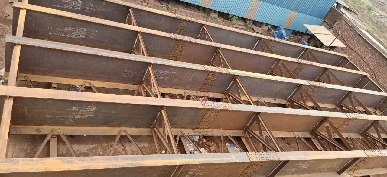
Bearings and Expansion Joints in Bridge Girder Packages: What to Confirm Before Fabrication
A bridge girder is only as useful as the points where it sits and where the deck can move. Bearings carry the load to the piers and allow for movement from temperature and traffic. Expansion joints close the gap between deck sections while allowing that movement. Both are often supplied by a specialist vendor, and both create interface risks that show up on site when a plate sits out of level or a hole does not line up. Most of those problems can be settled on paper before any steel is cut.
Confirm the bearing type and its scope
Start with the bearing type named in the design. Elastomeric, pot, spherical and sliding bearings each have different plate, anchorage and clearance requirements. Then settle who supplies what:
- The bearing itself, and the drawings the bearing vendor needs to design the interface
- The sole plate and masonry plate, and whether the fabricator welds or only supplies them
- The anchor bolts, their material, and whether they are cast in or drilled and grouted later
- The expansion joint, its brackets and any steel nosing, and the movement range the joint must accommodate
A clear scope sheet with a named owner for each item prevents the gap that appears between the bearing supplier and the girder fabricator.
Shop checks on the girder ends
Girder ends need the most attention. Check these items before the member is released:
- Stiffeners at the supports are in the positions the design shows and are aligned with the bearing centreline.
- Bearing plates are flat after welding. Welding distortion can lift a plate corner, so check flatness with the plate in its final assembled state, not only before welding.
- Machined or ground surfaces meet the specified finish where the drawing calls for one, and are protected until installation.
- Anchor and bolt holes match the bearing vendor's drawing. Check the positions against that drawing, not the girder drawing alone, because the two may have been issued at different revisions.
- Orientation marks show the direction of movement and the position of the fixed and free ends.
Expansion joint interfaces
Expansion joints depend on the gap set at installation. Confirm the design movement range, the reference temperature used for the gap, and whether the gap is set at fabrication or at erection. If the fabricator supplies the brackets or nosing, check their positions against the joint drawing and the girder ends they connect to.
Protection, marking and dispatch
Bearing plates, machined surfaces and joint components are easy to damage in transit. Store them flat, protect the machined faces, and mark each piece with its drawing reference and orientation. Coating over a bearing interface needs an agreed rule. The drawing should say whether a surface is coated, masked or left bare.
Pre-fabrication checklist
| Item | Confirm before cutting steel |
|---|---|
| Bearing type and vendor | Named in the design and in the scope sheet |
| Interface drawings | Issued by the bearing vendor and at the same revision as the girder drawing |
| Sole and masonry plates | Dimensions, flatness tolerance and who welds them |
| Anchor bolts | Material, position tolerance and installation method |
| Expansion joint | Movement range, reference temperature and gap-setting responsibility |
| Coating rule | Which interface surfaces are masked or left bare |
For the wider fabrication scope on bridge girders, see the girder bridge fabrication page. If you are preparing a girder package for enquiry, send the drawings for review and we will check the interface items against the scope above.
- bridge bearings
- expansion joints
- bridge girder
- sole plate
- bridge fabrication
About Kothari Chemicals (Engineering Division)
The Kothari Chemicals (Engineering Division) at Kothari Chemicals (Engineering Division) writes from day-to-day work in steel fabrication, quality assurance and project execution at the Bhilai works.